Creepage and Clearance Analysis in NEXTRA®
The creepage and clearance analysis in NEXTRA® is based on the ability of Nextra to exactly or approximately calculate the distances between powered elements within an electro-mechanical assembly.
Creepage is thus defined as paths on the surface of insulators between two powered elements. Clearance however is the path through air between two powered elements.
Relevant parameters that impact creepage and clearance violations are mostly identified and characterised in various standards, e.g. DIN EN 60664 (IEC 60664-1) in Europe, Germany or world-wide, respectively their sub-norms.
Using such standards minimum distance values between powered elements are to be defined for each application as input parameters that NEXTRA shall analyse within an electro-mechanical assembly to comply with.
If Nextra finds paths that underrun such mimum path lengths between two powered elements it identifies them graphically and in tabular form. The interactive analysis of such violating paths can then be performed in greater detail later on. The analysis results are associated with the design data and saved for later retrieval.
Creepage and clearance analysis in NEXTRA® is divided up into three modules: The 2d creepage analysis module identifies creepage violations on printed circuit boards without the need to facet or triangulate the model data. This is advantageous for performance and exactness of the analytical calculation. Furthermore there is no need for any manual intervention for the assignment of material information to the elements of the pcb as NEXTRA is aware of the material characteristic of the pcb's elements, which is a major parameter for the creepage analysis.
The clearance analysis in NEXTRA® honours all elements of the electro-mechanical assembly, being it the pcb of the mechanical parts of the assembly surrounding the pcb. The material characteristics of the pcb's elements are known, just the material characteristics of the elements of the mechanical parts need to be transferred during the import of the mechanical data or assigned interactively within Nextra.
The 3d creepage analysis is working on a representation of the facetted or triangulated model of the assembly which makes it appropriate for the mechanical parts of it. The same need for material information association is needed here as for the clearance analysis. If material information is assigned in any module it is reused in any other.
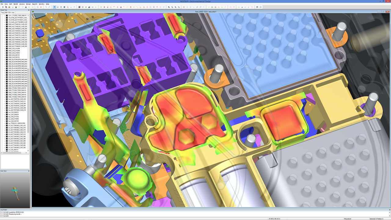
- Graphical representation of the Results of a Creepage Analysis of an Electro-mechanical Assembly in NEXTRA®

This image shows the graphical representation of the results of a clearance analysis of an electro-mechanical assembly in Nextra. Additional to a simple representation of the shortest paths of a violation as lines, Nextra can also display areas of connected violations - we call them hot-spots. Such hot-spots are displayed are surface areas with varying colours, ranging from distances way above the range in green, between a range changing from green via yellow to orange, and red below the minimum distance. This way critical areas can be easily identified without the need to interrogate numerical values from a table. The option to specify a range of interest is furthermore useful to consider tolerances from manufacturing or assembly.
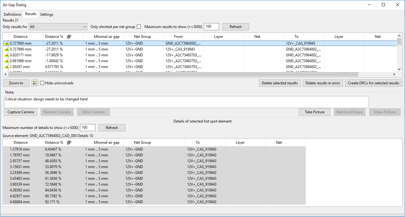
- Tabular Representation of the Analysis Results in NEXTRA®

The tabular result representation allows to identify all violations explicitly. Each violation tells the absolute distance, the relative underrun, the given range, the involved net groups and the identified elements with their nets and layers, respectively. By selecting a violation the 3d window can be asked to zoom to the violation and within the violation some element of the path can be selected. Then the information of the individual and the total path is highlighted. Furthermore uninvolved elements of the assembly can be hidden. The length of the individual segment is given both with the cumulated length of the path up to this segment.


